PC How Can I Shift a Saved Number to Left or Right?

Chase Brower

Steampunker
I've already looked into the thread about the binary counter with left shift, but this will not work (or at least must be modified in a way i can't seem to figure out) for what i am trying to create.

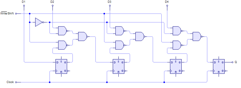
I'm working on a certain project, and in the project i want to have a saved number, and be able to shift the bits to the left or right each time a clock pulses, and furthermore be able to switch between shifting the number to the left or right.

I spent a ton of time trying to figure it out, but even when i do manage to make a design to shift to the left, i can't get it to shift to the right, and having 2 separate shifters would bring up the problem of having the saved value in sync. (This value is constantly being read on a display, and the right/left shifters would have to be interchangeably used, and the value on the display must not change except by shifting.)


For those wanting to know the project, it is a display that allows a "Dot" to move up, left, right, or down, and my goal is to achieve this through shifting 1 left to go left, 1 right to go right, or the same length as the display is left to go up, and vice versa to go down.
 
H'mm, can't your display simply check for new data on the clock pulse as well? I don't understand why the display needs to continuously read from the bus?
 
I'm assuming you want parallel in and parallel out..
You'll have to use a kind of shift register for this.
You'll have to use a line of D Flip Flops where the clocks are all hooked up to a single line, and each output is hooked up to the next input. You'll need 2 modes for this: a write function (to get the number in to the shift register), and then a shift function (to do shifting). To shift left or right, you just turn the line around.
Here's a reference image, although it is not exactly what you need. You'll need to do a bit of your own work to get it to work :p
4-Bit_PISO_Shift_Register.png
 
H'mm, can't your display simply check for new data on the clock pulse as well? I don't understand why the display needs to continuously read from the bus?
That makes more sense, and that will fix the problem of seeing it move up/down mid-shift and appearing glitchy, but my main problem now is figuring out the two-way shifter for data.

I'm assuming you want parallel in and parallel out..
You'll have to use a kind of shift register for this.
You'll have to use a line of D Flip Flops where the clocks are all hooked up to a single line, and each output is hooked up to the next input. You'll need 2 modes for this: a write function (to get the number in to the shift register), and then a shift function (to do shifting). To shift left or right, you just turn the line around.
Here's a reference image, although it is not exactly what you need. You'll need to do a bit of your own work to get it to work :p
4-Bit_PISO_Shift_Register.png

Would you think it would be possible to have it shift left and right interchangeably? With only being able to shift left, or only being able to shift right, my display could only render up/left movements, or down/right movements. I'll try testing with design and D-flip flops, as i had been using and gates and the new transistor (faulty lamp). Hopefully the D-flip flops will allow for some more flexibility.
 
That makes more sense, and that will fix the problem of seeing it move up/down mid-shift and appearing glitchy, but my main problem now is figuring out the two-way shifter for data.


Would you think it would be possible to have it shift left and right interchangeably? With only being able to shift left, or only being able to shift right, my display could only render up/left movements, or down/right movements. I'll try testing with design and D-flip flops, as i had been using and gates and the new transistor (faulty lamp). Hopefully the D-flip flops will allow for some more flexibility.
It is possible.. I've done 4-way before. You need an a line of D Flip Flops for each direction. They have to go in to each other, and write to each other, but only shift one direction at a time.
 
I DID IT!!!!!

At first i thought it didn't work, and after about 20 minutes i figured out that i was because my wires weren't connected to my switches.-_-

Anyways, it uses 2 seperate clocks to shift the saved value left or right. Now that i made it, i no longer fully understand it, and since it is near my build... i might just hook it up to it. Just kidding, although it's gonna take a bit to recreate it. (get it? bit? ..... sorry.)

 
Capture 2016-06-03 18_53_48.png

The blue and red wires at the bottom are the outputs, the two yellow wires are the clocks, and the switch all the way on the right is the data input. Because of the machine i made with this, the data input is almost never used (except to start the machine the first time it is used).

All the wires in the middle are a giant mess that i no longer understand.
 
View attachment 115251
The blue and red wires at the bottom are the outputs, the two yellow wires are the clocks, and the switch all the way on the right is the data input. Because of the machine i made with this, the data input is almost never used (except to start the machine the first time it is used).

All the wires in the middle are a giant mess that i no longer understand.
I'm trying to understand it but I honestly don't get it either XP but its still really neat! I might use something like this in a future build... I have a couple ideas for something crazy! :)
 
1. Ok, so the data input turns on the lamp (green AND gate) all the way at the right.

2. This lamp activates the 2 transistors near it, meaning the clock pulse will go through them if activated.

3. If the clock pulse flows through the transistor to the left of a lamp, then it pulses to deactivate that lamp, and activate the one to the left of it. If the clock pulses and activates the transistor to the right of the lamp, it will deactivate it, and activate the one to the right of it.

4. This effectively means that pulsing the "left" clock will make any stored bits move to the left, and pulsing the "right" clock will make any stored bits go to the right.


That's my best go at an explanation, i hope it's easy to follow :p
 
I'm still trying to understand it... I don't understand how the wiring works.. I understand how they can go left and right... but when I'm used to seeing shift registers, its the kind with the D Flip Flops and stuff... I really wish I could understand this better. I'm trying to make a.. sort of 4-way shift register.. where it can also be carried upwards and downwards.
 
Cool. So this is like 2 super-imposed, oppositely directed, sequential counters (or however you want to term these circuits): http://forums.terraria.org/index.ph...logic-circuits-with-faulty-logic-gates.44319/
Completed basic circuit
ANoHMtz.png
SlimyElementaryAfricanpiedkingfisher.gif

As you can see in the gif, every 5 times the switch is flipped, the torch is turned on/off.
With added AND gate relay to reset bother direct components of each conjoined bit.

I believe @inomanoms, for one, had a go at making (hoiktronic) bit shifters with a Rubiks Cube build in mind, so yeah:
sort of 4-way shift register.. where it can also be carried upwards and downwards.
Would be dead handy for that. And then figuring to how to shift a 6 colour representation, not just a binary value.
 
Last edited:
how to shift a 6 colour representation, not just a binary value.
maybe 3 overlapping quad-direction shift things... each for a bit. and then each gets converted to decimal? But then.. How would you do colors? I've been looking for a way to sort of swap colors in the same coordinate, but doesn't look like its possible. If only Terraria had pistons to move blocks x3

Also, I looked at the shift design you posted... How do I get an output from each? I tried that, but the torch would stay on after it shifted past that area
 
Last edited:
ahh, yes, I tried this as well :) My issue though.. Is that.. well, the direction needs to be determiend through AND gates, the output only pulses once from the double-transistor thing. this leaves the AND gates in an ON state. I tried hooking up the outputs of both transistors to the next pair, but that doesnt work and glitches the logic.

 
You have the pulse from the lamp after reset the torch under the lamp before.
Yes... but then... you'd need that to go 4 directions and come from 4 directions, as well as the output going 4 directions and input coming from 4 directions. You'd need 16 total wires.. 4 on each side. of each cell. And would the AND gates still be broken?
 
Back
Top Bottom