An explanation of logic gates

Was this helpful?

  • Yes

    Votes: 10 100.0%
  • No

    Votes: 0 0.0%

  • Total voters
    10
Is anyone else SUPER confused about logic gates? Like what the heck is a XNOR gate? Being sick of not knowing what they were, I finally found a reliable source and learned about logic gates earlier today, so now I am here to share my knowledge with the world!

To start off, there are 7 main types of gates: AND, OR, XOR, NOT, NAND, NOR, and XNOR. Every gate but the NOT gate (also called an Inverter) has 2 inputs and 1 output. I will include the symbol for each gate (symbols aren't important unless you are drawing a circuit). Also, 1=True=Active (in-game) and 0=False=Inactive.

AND
AND gates work on a simple principle: if both inputs are true, the output is true. Any other combination makes the output false. These are the logic gates that have been seen in spoilers. As you can see, the output on the bottom only works if both things on top are active.
31r5w1R.gif
upload_2016-5-15_22-8-40.png

OR
OR gates' output will be true if either input is true. That means that the only false output is with two false inputs.
upload_2016-5-15_22-23-39.png

XOR
These are like OR gates, except that if both inputs are true the output is false. Therefore, if the inputs are the same, output is false and if the inputs are different output is true.
upload_2016-5-15_22-24-6.png

NOT (Inverter)
This gate only has ONE input. What it does is invert the input. True=false and false=true
upload_2016-5-15_22-26-4.png


NAND
Acts like an AND gate immediately followed by a NOT gate. This means that all outcomes are true except for when the inputs are both true.
upload_2016-5-15_22-26-36.png (Looks like an AND gate with a circle)
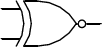
NOR
OR gate followed by a NOT gate. Every outcome is false except when the inputs are both false.
upload_2016-5-15_22-28-18.png

XNOR
XOR gate followed by a NOT gate. Outcome is true when inputs are the same.
images


So those are the 7 main logic gates! If the outcomes confused you, you can search "(AND, OR, etc.) gate truth table" and images will come up with tables on the outcomes.
 
Nice guide! I'm getting a bit rusty since the last time I worked with electronic circuits. This will come in handy.
 
Just want to point out that in Terraria there are essentially only two basic logic gates. This is because Terraria is a pulse-based system, so the inputs and outputs are arbitrarily defined. In real life logic gates, a "true" signal indicates current is being generated, but in Terraria there are no sustained currents. Instead, a "true" output can be assigned to a torch that is either on or off, or to a block that is either actuated or deactuated.

So in Terraria the AND/NAND, OR/NOR logic gates are identical except for how we label the TRUE and FALSE states of the inputs and output, so that's one type of logic gate, and the XOR/XNOR is the other type of logic gate. NOT gates in pulse-based systems are also meaningless, which is why they get excluded from the list.

I'd also suggest to anyone wanting to learn about logic gates (in Terraria at least) to actually try replicating some of the machinery that uses them. The best way to learn is through application!
So at the end, we will have just two logic gates, right? I have always been excited about which things can be done with all those logic gates, in fact, i was expecting about "micro"chips designed in Terraria...
 
So at the end, we will have just two logic gates, right?

Not exactly. We have just two basic gates, but we also have an unlimited number of "giant logic gates". Giant gates have any number of inputs (N) and a maximum of 2^N outputs.

Here are some examples. For each build, the inputs are at the bottom, and the outputs are vertically on the right:

HlXsDxs.png


Link to explanation thread:

http://forums.terraria.org/index.ph...cs-video-tutorial-on-giant-logic-gates.32700/

I have always been excited about which things can be done with all those logic gates, in fact, i was expecting about "micro"chips designed in Terraria...

Like this? ;)

N88d2hj.jpg


Here's an even bigger build:

eiY266M.jpg
 
Last edited:
If I'm not mistaken, OR/NOR/AND/NAND gates in Terraria are multary (as they should be), i.e. they can take any number of inputs. I'm not certain about XOR/NXOR, but since any change in input of an XOR gate causes a change in output, and since Terraria is pulse-based, there is no functional difference between an XOR gate and a diode ("one-way street") anyway.
 
If I'm not mistaken, OR/NOR/AND/NAND gates in Terraria are multary (as they should be), i.e. they can take any number of inputs. I'm not certain about XOR/NXOR <snip>

In Terraria gates that have the XOR/XNOR function can also be designed to take in any number of inputs. However, unless you're trying to emulate real-world electronics using basic logic gates, there's no need to think of the basic gates when it comes to Terraria electronics, since we have the ability to create single giant gates that simulate any possible combination of basic gates. For instance, we can construct a single giant gate for a full adder, whereas real world full adders are usually a combination of AND and XOR gates.
 
Not exactly. We have just two basic gates, but we also have an unlimited number of "giant logic gates". Giant gates have any number of inputs (N) and a maximum of 2^N outputs.

Here are some examples. For each build, the inputs are at the bottom, and the outputs are vertically on the right:

HlXsDxs.png


Link to explanation thread:

http://forums.terraria.org/index.ph...cs-video-tutorial-on-giant-logic-gates.32700/


Like this? ;)

N88d2hj.jpg


Here's an even bigger build:

eiY266M.jpg
Now, it's time to play Terraria in Terraria!
 
Just my two-cents on the matter (outside of Terraria):

Of the 7 types listed, 4 are primary gates: NOT, AND, OR, XOR.

The other three (NAND, NOR, XNOR) are just offshoots (the AND, OR, and XOR combined with a NOT, respectively).

Some may find it easier to understand (and remember) the first 4 and the other three just invert the output. It reduces the number of truth tables down to 3 you need to memorize. (Technically 4 tables, but I don't really consider the NOT table a table... ^_^) I've tutored a few people in logic gates and that what I usually tell them if they need to memorize the outputs. I was taught logic gates via the Truth Table method and getting that drilled into me. (High-school digital electronics elective class.)

Also, you can construct any other gate with just an array of NAND or XOR gates. (In fact, I think one of the exercises we did in that high school class was designing/building said array circuits.) So if you ever need/want to buy a ton of logic gates, NANDs and/or XORs are the safest bet. (You'd just need a lot of space for the resultant circuitry.)

Wikipedia (at least the EN version) has plenty of useful info with diagrams. It's worth the read if anyone is interested. (It even has the alternative NAND/NOR arrays diagrams for each gate.)
 
Considering all the commotion around logic gates being implemented, i'm sure this will come in handy. I predict only hours after the update will we see the updated versions of most of the mechanisms currently in T-MEC :)
 
Ok, so I thought that this meant how to make the logic gates in Terraria, but I wasn't disappointed, as many need to know this.
I know that you can make all gates from NAND gates. Crazy right?

You have one input, which goes into both A and B slots for a NAND gate. This is a NOT gate, because one signal is both signals.
With two inputs, one NOT (which is made of the NAND) goes after the NAND which A and B go into. There's your AND

For OR, put A into both slots for one NAND and B similarly. Then put the outputs into another NAND. Or just invert both A and B and put it into a NAND
NOR is OR+NOT, so the output goes into both inputs.

XOR is a hard one. Put A in one input for two NANDs. Put B in the other input of one of them, and the other input is not connected with A's second. That first NAND goes into both the inputs of the other NANDs that A and B went into alone. The outputs of those go into another NAND.
here's a picture.
XNOR is just that and the input is NOT the XOR (that's clearly how the NOTs, NANDs, NORs and XNORs got their names)
They also can be made of NOR gates, which makes the two gates "universal". I wonder if you can make other gates with an XNOR!

You also forgot one: The Buffer Gate. While it's pointless in Terraria (which is probably why you counted it out, as it's not exactly considered a gate) as there are no signal strength thingies in the game, it is used in real life as an extra energy source. It's two NOTs, each of which send a fully charged signal in its output, making any signal (except a lack thereof) as strong as can be.

EDIT: It's not loading the picture. Just search "how to make an xor gate out of NAND gates" and it's the first few pictures.
 
You also forgot one: The Buffer Gate. While it's pointless in Terraria (which is probably why you counted it out, as it's not exactly considered a gate) as there are no signal strength thingies in the game, it is used in real life as an extra energy source. It's two NOTs, each of which send a fully charged signal in its output, making any signal (except a lack thereof) as strong as can be.
I've never really consider that to be a gate in the typical sense... That being that you using it to manipulate logic outputs. It's just a signal repeater/booster in the end. Most circuit designs only implement those as a last resort. It's more components, area, power, cost, complexity, latency/lag, etc. in a design that doesn't really do anything useful (that is, contributes to getting calculations done). About the only place you're gonna see something like that in at or along device interconnects. (At which point I would have to ask why the devices are so far apart and/or using signal voltages so low that repeaters are needed.)

They can be justified (as I alluded to above), but it's not one of the things you would automatically include in a design unless you actually need it and there is no getting around it. (e.g. Circuit board layout restrictions.)

Actual "buffers" (temporary storage space) are useful and used all the time, however.

As an example of something that used buffering for signal integrity, Intel used to have a line of CPU's and chipsets that supported Fully-Buffered RAM (or FB-DIMMs). They ran bloody hot (well, for RAM at least) and added latency to RAM access. FB-DIMMs didn't last long in the scheme of things. The only physical benefit was it saved pin counts between the memory controller and the RAM modules. Other benefits were supposed to be increase bandwidth and DIMM capacities. Wasn't enough to save the standard though.

The reason for the buffering (signal boosting) was because FB-DIMMs used a high frequency serial connection to the Memory controller (contemporary designs use one or more parallel connections, usually in increments of 32-bits, at lower frequencies). High frequencies have inherent issues with signal integrity. (Exercise: Try waving your hand between two points slowly, then speed it up. See how accurate your movements are as you increase the speed. Similar idea here.) It was a reasonable design, just not very practical.

(The buffer chip was actually a memory controller itself as well. It had to translate the serial signals to parallel signals because the actual memory chips still had 32-bit connections. They were off-the-shelf chips rather than purpose-made. Another reason FB-DIMMs didn't last.)

On the flip side, standard server grade RAM is typically registered (a.k.a. buffered). This allows more RAM to be connected to a memory controller. You do have a latency penalty (like 1 clock cycle), but servers tends to place higher worth on capacity and reliability then a miniscule penalty in access times.
 
Last edited:
Guys... GUYS! (And girls too ;) )

No need to worry about building each and every logic gate using one or the other. According to the notes on the upcoming 1.3.1 update HERE there will be all of the above logic gates as seperate blocks. This surely is confirmed (to some extent) if you look at Wire Bridge screenshot, where we have 3 types of logic gate blocks, all of them present in their active and inactive states.

Deducting on the activation examples, all green is AND, green in two squares is NOT, green and 2 red is XOR. Well if i'm not wrong here...
 
Last edited:
@Ranadiel Yes. We know. It's a "build a gate". There are probably going to be people with an understanding of Boolean logic, who are going to make some crazy reductionist gates, but for the lay person, covering the basic logic gates might be useful, so that they can build some cruder set ups with the basic gates. Which is the point of this thread, I'm guessing.
 
Just written down a simple multi-output logic gate using the new "blocks". My contribution to the topic i guess :)

Terraria-Multiple outputs.png

A - Source of the main input (for example, teleportation signal)
B - Varying switch
How it works: A signal is connected to two AND gates. B signal is connected directly to the second and through a NOT gate to the first. This means that the signal is only generated when A is on, discerning between OUTPUT1 and OUTPUT2 (as shown in the results table).

One thing is certain - Using standard logic gates will be more compact in most of the mechanisms. Although i have one major problem:
How will teleporter signal be treated through logic gates? Will one be able to take advantage of it or not? Multiple routes possible through logic gates?

If it's going to be possible, it will allow to build a teleporter hub strictly using logic gates at various junctions. But if not... Only hoiks for teleportation logic gates?
 
How will teleporter signal be treated through logic gates? Will one be able to take advantage of it or not? Multiple routes possible through logic gates?

Well, sure. I mean, we can do it already, but instead of using an hoiking actor external to the character to provide the signal to move the character from one teleporter to another, we just use the character himself. So, yes.

I'm guessing the underlying system of nearest/longest wire length will remain true with teleporters, so you would have to break up the gate geographically.
 
Well, sure. I mean, we can do it already, but instead of using an hoiking actor external to the character to provide the signal to move the character from one teleporter to another, we just use the character himself. So, yes.
I meant using the new logic gates. There's no information that a teleporter signal can be used through the "block logic gate". The old ones using hoiks or tracks sure, but that requires a lot more space to work.
 
Um, sort of missed some stuff...
I guess I'll just let you guys discuss it, because I am really not the one to ask. I learned this two days ago.
 
Back
Top Bottom